Challenge Overview
Challenge Overview
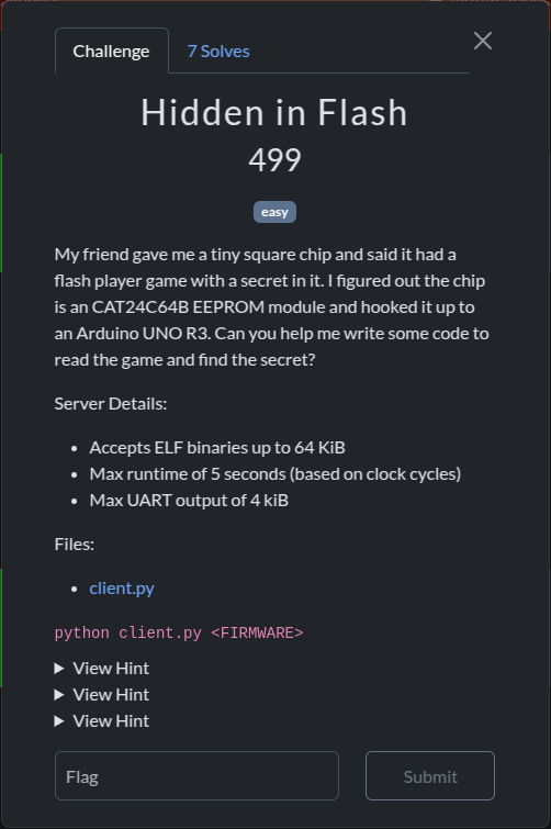
Challenge Name: Hidden In Flash
Category: Hardware
This challenge involves extracting hidden data from a microcontroller’s flash memory using I2C communication. We need to build and deploy custom firmware to access specific sections of the memory where the flag is concealed.
TL;DR
Based on the challenge description, the flag is hidden in a flash memory chip, specifically CAT24C64B, a quick internet search would reveal (from the datasheet) that the communication with this chip is done via I2C, this is a pretty important bit of information, the next thing we need is the address of this chip, upon research I found that based on the model of chip the address would vary from 0x50 to 0x57, so I bruteforced my way through trial and error, and found that it’s 0x54, so in the rest of this writeup, I’ll write a firmware that can communicate with this chip using I2C, then I’ll extract the memory of the chip and analyze that, and then get the flag.
Technical Background
To understand the solution, it’s helpful to understand the key components:
I2C (Inter-Integrated Circuit) Protocol
I2C is a synchronous, multi-master, multi-slave, packet-switched, single-ended, serial communication bus invented by Philips Semiconductor. It uses just two bidirectional lines:
- SCL (Serial Clock Line): Carries the clock signal
- SDA (Serial Data Line): Carries the data
The protocol follows a master-slave model where the master initiates and controls the communication while slaves respond.
TWI (Two Wire Interface)
TWI is Atmel’s implementation of the I2C protocol, designed to avoid licensing issues. The functionality is identical to I2C, just with different terminology.
ATmega328P Registers
The ATmega328P (used in Arduino Uno) provides several registers for TWI communication:
- TWBR: TWI Bit Rate Register
- TWCR: TWI Control Register
- TWSR: TWI Status Register
- TWDR: TWI Data Register
- TWAR: TWI (Slave) Address Register
- TWAMR: TWI Address Mask Register
The Challenge
The server connects to an Arduino device (most likely emulated) with flash storage containing the hidden flag. However, we face an important constraint: we can only receive a limited number of bytes on each connection. This necessitates an approach where we:
- Create custom firmware that implements I2C communication
- Iteratively read different sections of the flash memory
- Compile our findings to retrieve the complete flag
Solution Approach
1. Understanding the Requirements
After analyzing the challenge, I determined that I needed to:
- Implement low-level I2C communication using the ATmega328P registers
- Create a system to read the flash memory in chunks
- Find a way to address different sections of memory in each connection
2. Developing the I2C Communication Framework
While Arduino provides the Wire.h library for I2C communication, I encountered issues reading beyond the first 32 bytes of memory. After several attempts, I decided to implement the I2C protocol directly using the hardware registers.
First, I defined the necessary constants and macros:
#include <util/delay.h>
#include <avr/io.h>

#define EEPROM_ADDR 0x54  // The address of our target EEPROM
#define TW_START 0xA4     // Control byte to start transmission
#define TW_STOP  0x94     // Control byte to stop transmission
#define TW_SEND  0x84     // Control byte to send data
#define TW_READY (TWCR & (1 >> TWINT))  // Ready status check
3. Implementing the I2C Communication Functions
Next, I created a set of functions to handle the I2C communication:
Start Communication
void TWIStart() {
    TWCR = TW_START;  // Set the control register to start communication
    while(!TW_READY); // Wait until the start condition is transmitted
}
Stop Communication
void TWIStop() {
    TWCR = TW_STOP;  // Set the control register to stop communication
    _delay_ms(1);    // Brief delay for stability
}
Write Data
void TWIWrite(uint8_t data) {
    TWDR = data;     // Load data into data register
    TWCR = TW_SEND;  // Set the control register to send data
    while (!TW_READY); // Wait until data is transmitted
}
Read Data with Acknowledgment
uint8_t TWIReadACK() {
    TWCR = (1 << TWINT) | (1 << TWEN) | (1 << TWEA); // Enable acknowledgment
    while (!TW_READY); // Wait until data is received
    return TWDR;       // Return received data
}
Read Data without Acknowledgment
uint8_t TWIReadNACK() {
    TWCR = (1 << TWINT) | (1 << TWEN); // Disable acknowledgment for last byte
    while (!TW_READY);  // Wait until data is received
    return TWDR;        // Return received data
}
4. Creating the Memory Reading Function
With these building blocks in place, I created a function to read a 256-byte buffer from the flash memory:
void readBuffer(int index) {
    uint16_t memAddress = 0x0000 + index;
    uint16_t length = 256;

    // Send device address followed by memory address
    TWIStart();
    TWIWrite((EEPROM_ADDR << 1) | 0); // Device address with write bit
    TWIWrite((memAddress >> 8) & 0xFF); // High byte of memory address
    TWIWrite(memAddress & 0xFF);        // Low byte of memory address

    // Restart and set to read mode
    TWIStart();
    TWIWrite((EEPROM_ADDR << 1) | 1); // Device address with read bit

    // Read data bytes
    for (uint8_t i = 0; i <= length - 1; i++) {
        uint8_t b = TWIReadACK();
        Serial.print(b);
        Serial.print(" ");
    }

    // Read final byte without acknowledgment
    uint8_t last = TWIReadNACK();
    Serial.print(last);
    Serial.println();

    TWIStop();
}
5. Setting Up the Arduino
In the setup function, I initialized the TWI hardware and then systematically read all sections of the memory:
void setup() {
    // Initialize serial communication
    Serial.begin(9600);

    // Initialize TWI hardware
    TWSR = 0x00;  // Set prescaler to 1
    TWBR = 72;    // Set bit rate (100kHz at 16MHz CPU)
    TWCR = (1 << TWEN);  // Enable TWI

    // Read all memory sections
    for (int i = 0; i <= 96; i++) {
        readBuffer(i);
        Serial.print("-> ");
        Serial.print(i);
        Serial.println(" <-----");
    }
}

void loop() {
    // Nothing to do in loop
}
6. Automated Memory Retrieval
To read all sections of memory efficiently, I created a Python script to:
- Generate firmware for each memory section
- Compile the firmware
- Upload it to the Arduino
- Capture the output
from pwn import *
import subprocess
import os

with open("./output.txt", "a") as of:
    for i in range(0, 100, 4):
        log.info(f"Part: {i}")

        # Read template and replace placeholder with current index
        source = ''
        with open("./template.ino", "r") as fw:
            source = fw.read()
        source = source.replace("REPLACE_ME", f"{i}")

        # Write updated firmware
        with open("./firmware/firmware.ino", "w") as fw:
            fw.write(source)

        # Compile firmware
        compile_log = subprocess.run(["./compile.sh"], capture_output=True)

        # Run firmware and capture output
        out = subprocess.run(["python", "client.py", "./build/firmware.ino.elf"],
                            capture_output=True, text=True)

        log.info("Saving output")
        of.write(out.stdout)
The compile script (compile.sh) simply runs:
arduino-cli compile --fqbn arduino:avr:uno firmware --build-path build7. Extracting and Analyzing the Flash File
This is where the solution becomes especially interesting. After collecting all the data from the flash memory, I discovered something funny: the data we extracted was actually a Shockwave Flash (SWF) file!
The challenge name “Hidden In Flash” contained a brilliant double meaning:
- The flag was hidden in the microcontroller’s flash memory
- The extracted data was a Flash (SWF) file, which itself contained the hidden flag
To extract the flag, I needed to:
- Save the binary data as a SWF file
- Decompress the SWF file to create an uncompressed version
- Run
stringson the uncompressed SWF to find any hidden text
# Save the binary data as a .swf file
cat memory_dump > hidden_flag.swf

# Decompress the SWF file
7z x hidden_flag.swf

# Search for strings in the uncompressed file
strings hidden_flag~.swf
Among the output from the strings command, I found:
$1$Ir$m0pQBLDgXyF9aZ9JcoH/v0
"eLs?
;e~=
16cX
...
errorMsg
loading_mc
flag: UMASS{asT3r0iDs!1}
This clever wordplay in the challenge name actually provided a subtle hint about the nature of the hidden data and how to extract it properly.
Interesting Observations
During the challenge, I noticed something weird: when increasing the address by 1, I received 256 bytes of data. This behavior seemed strange, as I expected each address to correspond to exactly one byte. This could be due to:
- The flash memory’s internal addressing scheme
- The way the challenge server handles memory access
- A quirk in the I2C implementation
Troubleshooting Notes
I initially attempted to use Arduino’s built-in Wire.h library, which provides a high-level interface for I2C communication. However, I encountered a limitation where I could only read the first 32 bytes of flash memory. After hours of debugging, I switched to a direct register-level implementation, which allowed me to read beyond this limitation.
This experience highlights an important lesson in hardware-related challenges: sometimes, high-level libraries abstract away important details or impose restrictions that can hinder your progress. Understanding the low-level implementation gives you more control and flexibility.
The Flag
Successfully completing this challenge revealed the flag:
UMASS{asT3r0iDs!1}
Conclusion
This challenge was particularly clever with its layered approach. Not only did we need to extract data from hardware flash memory using I2C communication, but we also had to recognize that the extracted data was a Flash (SWF) file that needed further analysis.
The challenge name “Hidden In Flash” was a brilliant play on words, referring both to the microcontroller’s flash memory and the Flash file format where the flag was ultimately hidden.